
Table of Contents
Introduction
I found a nifty little brushless motor driver on Amazon for around 20 bucks that can be used for controlling a hoverboard motor. This is a great board that makes it easy to control a hoverboard motor. Naturally after testing and playing with it the next step is to connect it to an Arduino. This guide shows how I connected the motor controller to an Arduino and shows some example programs that can be a good starting point for your own hoverboard projects.
But first if you haven’t seen my post on the motor controller check it out here:
You can also watch the Youtube video that goes along with this post:
Arduino Controlled Hoverboard Motor – Video
I plan to make a video that compliments this guide soon. I will post it here when it is complete.
< VIDEO COMING SOON>
Parts List
Here is a list and brief descriptions of the parts I used in this project.
- Hoverboard Motor/Wheel
- Battery or other Power Supply
- RioRand 400W 6-60V PWM Brushless Motor Driver
- Arduino
- Battery Connectors
- Jumper Wires
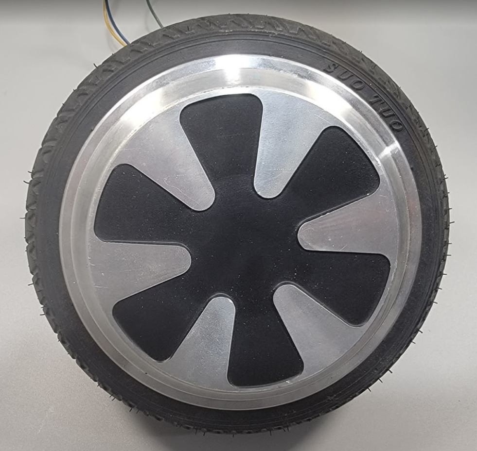
Hoverboard Motor/Wheel
The first thing you are going to need is a hoverboard motor. The motor is a brushless DC motor that is built into the hoverboard wheel. It is best if you can find somebody with an old broken hoverboard and take it apart. Or if you have some money to blow buy a brand new one and take it apart like I did. I later found somebody selling old broken hoverboards for $20 each and snatched 3 of them.
Amazon Link: https://amzn.to/3UkjYoO
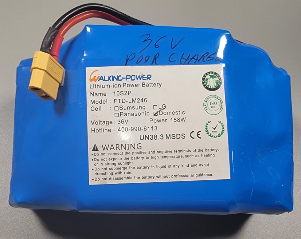
Battery or other Power Supply
The next item you need is a battery or a power supply that can supply enough voltage and current to drive the motor. I was able to get 2 good batteries out of the 3 broken hoverboards I bought. The 3rd one has some damaged cells and won’t hold a charge.
The battery packs out of most hoverboards are Lithium-ion 10S2P and are 36V 158W. The 10S2P means there are 20 individual cells with two sets in parallel of 10 cells in series.
Amazon Link: https://amzn.to/3U9hw4P
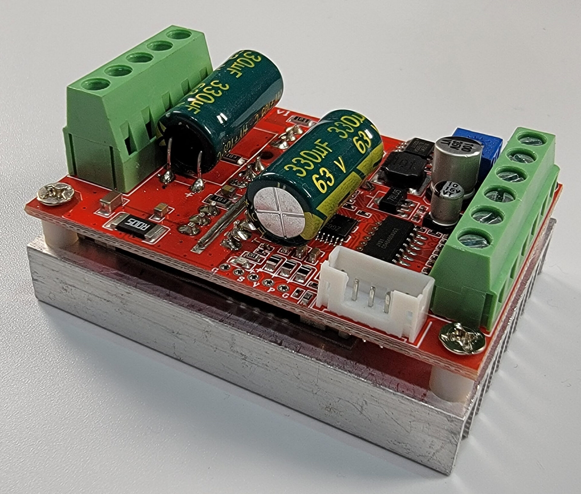
RioRand 400W 6-60V PWM Brushless Motor Driver
This is a nice little board that makes controlling the hoverboard motor really easy. It has inputs for the motor direction, brake, and speed control. It also has an output for measuring the motor speed. It goes for around $20 USD on Amazon or E-Bay.
Amazon Link: https://amzn.to/3zR5m8v
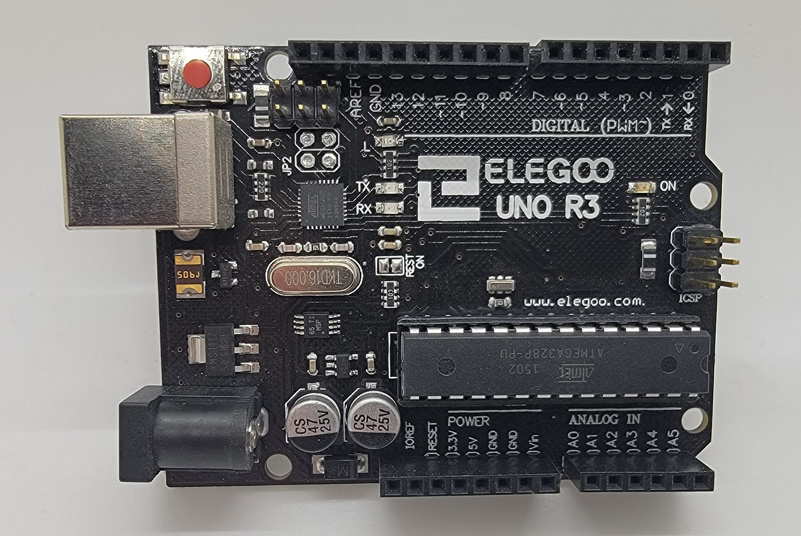
Arduino
There are many flavors of Arduino boards out there, and almost any of them will work. I decided to use the Elegoo Uno R3. It works well, is inexpensive, and has good availability… at least in the USA.
Amazon Link: https://amzn.to/3WLj0nE
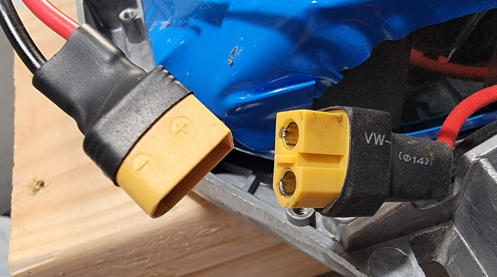
Battery Connectors
You may need some extra battery connectors. Most hoverboard batteries us the XT60 connector.
Amazon Link: https://amzn.to/3hhvAL6
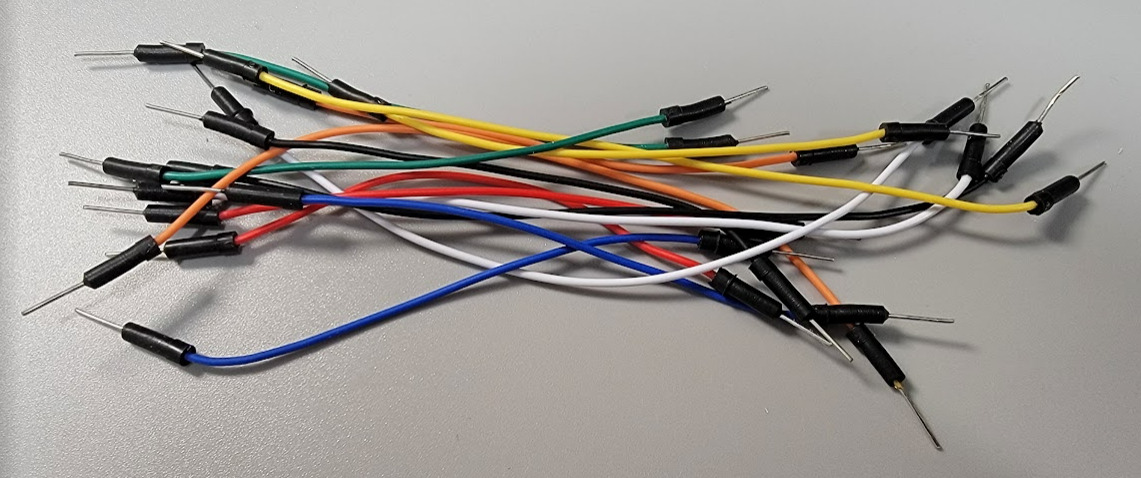
Jumper Wires
I use these jumper wires to make the connections between the motor controller and the Arduino.
Amazon Link: https://amzn.to/3DJaXii
Wiring Guide
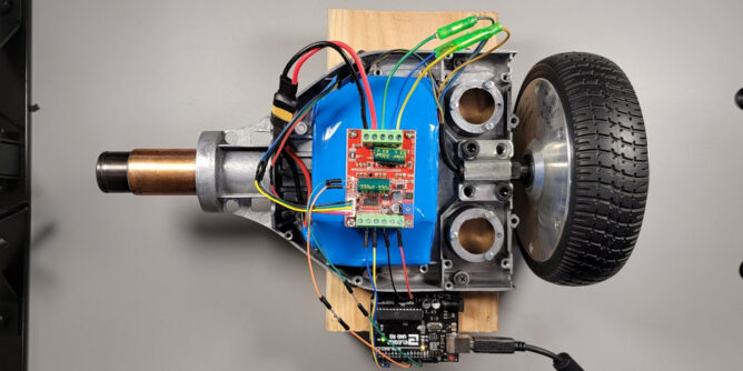
The image below shows how I wired the motor controller board to the hoverboard motor and Arduino. A couple things to remember is the on board potentiometer must be adjusted all the way counter-clockwise when using PWM control. Also the two pin jumper must be shorted when using PWM control. This can be done by soldering a blob of solder across the two pins or soldering in a wire jumper.
I am powering the Arduino from the USB cable. When used in a device without the USB cable you will need a way to power the Arduino. This is typically done by applying 7-12V to the Barrel connector or the VIN pin. A 9V battery should work for this or you could get a DC to DC regulator that converts the 36V Lithium-ion battery voltage down to the 7-12V rage. Another option is to apply 5V directly to the 5V pin of the Arduino, this does bypass some of the Arduino’s protection circuitry so only do this if you have other protection circuitry in place or have money to blow on a new Arduino board if/when you fry one.
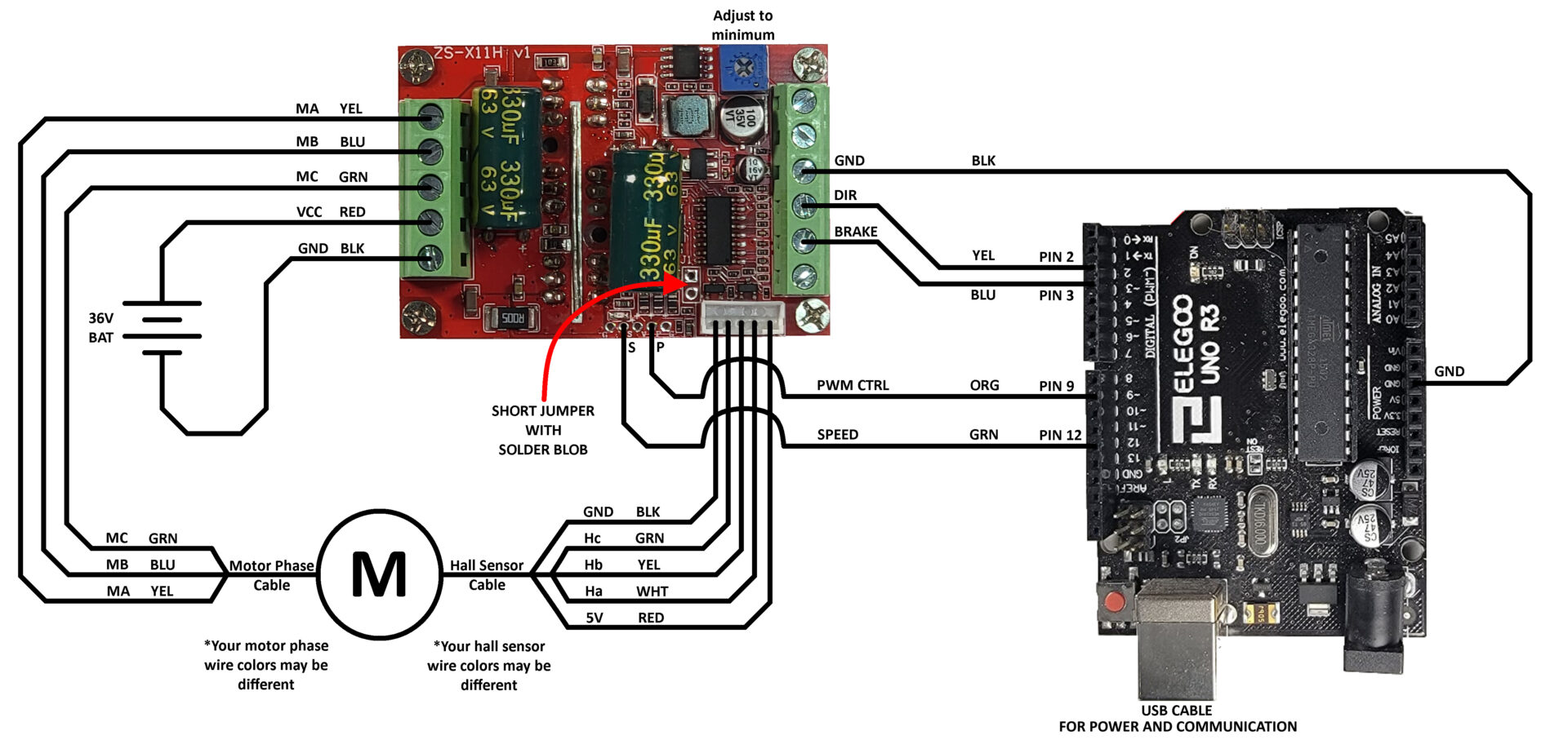
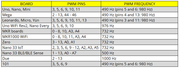
I selected the Arduino pins above because they made the schematic layout easy to read. For the DIR, BRAKE, and SPEED connections you can use any of the digital input/output pins. For the PWM control line you need to make sure to use one of the pins capable of PWM output. On the Arduino Uno R3 board the PWM pins are marked with a tilde character “~”. Here is a table that lists what pins are available to use for PWM output for some of the Arduino boards.
Here is a picture of my test setup that shows how it is wired:

Programming
Arduino PWM
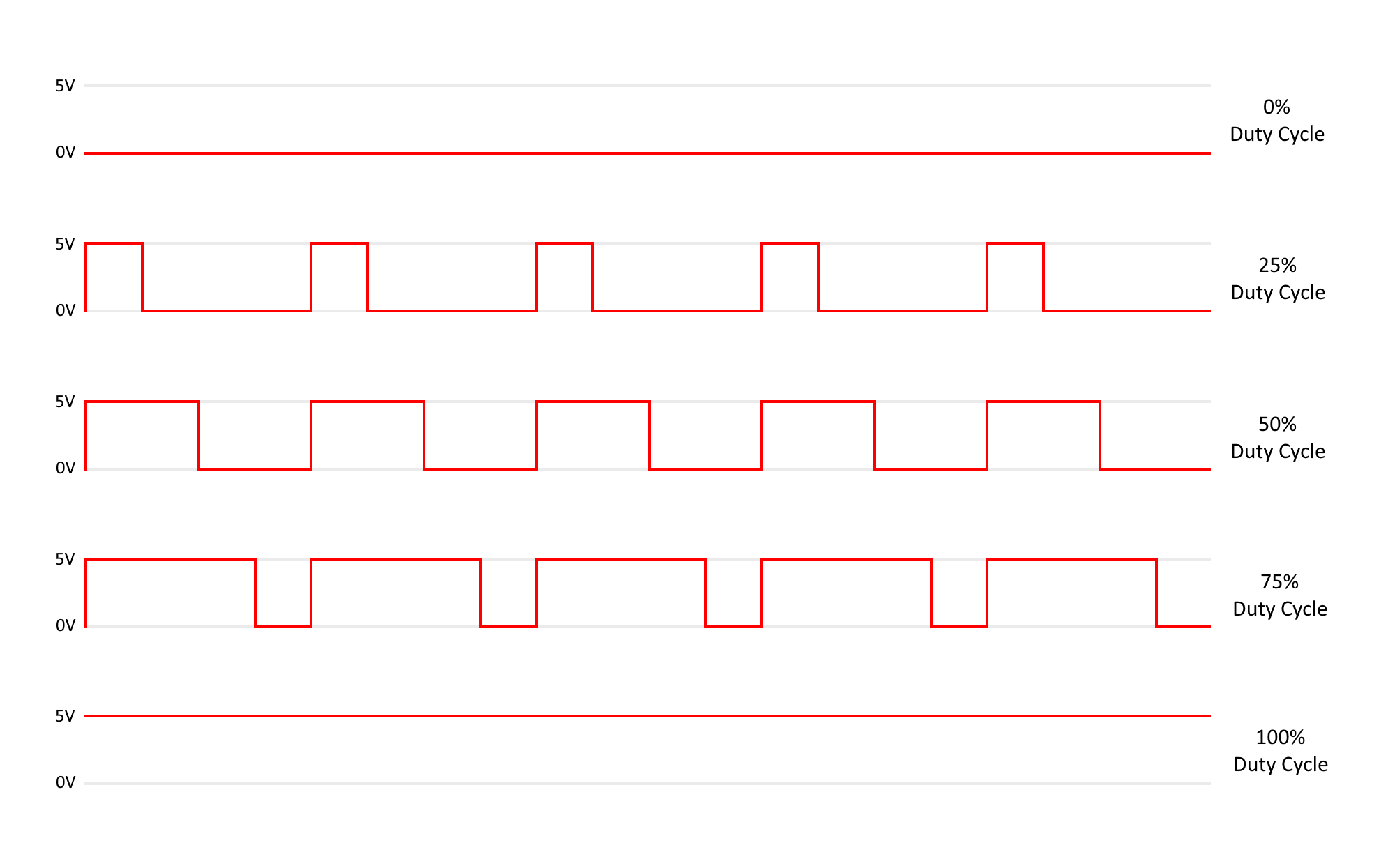
A PWM signal has a fixed frequency but changes the duty cycle to communicate data. A duty cycle of 0% (constant low) will not drive the motor causing it to be in a free spin state. A duty cycle of 100% (constant high) will drive the motor at full speed. Any duty cycle percentage between will drive the motor at different speeds.
On a side note, this motor controller does not use the same PWM signal as an RC servo uses. So connecting this motor controller to something designed to control an RC servo will not work correctly.
pinMode() Command
To output a PWM signal on one of the Arduino pins, you need to first setup the pin for output. This is typically done in the setup() function so it only gets called once.
The pinMode command has two arguments, first is the pin number. Second is the mode, which can be INPUT, OUTPUT, or INPUT_PULLUP.
void setup()
{
    pinMode(9, OUTPUT);
}
More information on the pinMode command can be found here:
https://docs.arduino.cc/language-reference/en/functions/digital-io/pinMode/
analogWrite() Command
To set the PWM duty cycle you use the analogWrite command. The PWM frequency is setup deep in the Arduino libraries. There is a way to change the frequency but for most things the default frequency works. The duty cycle can be adjusted by sending a number from 0 to 255 where 0 is 0$ and 255 is 100% duty cycle. For example 127 would be approximately 50% duty cycle.
The analogWrite command has two arguments, first is the pin number. Second is the value that represents the desired duty cycle (0 – 255).
void loop()
{
    analogWrite(9, 127);
}
More information on the analogWrite command can be found here:
https://docs.arduino.cc/language-reference/en/functions/analog-io/analogWrite/
Example Program – PWM_Oscillating
This example program increments the PWM duty cycle by 1 every 20ms until it gets up to 255, then it decrements the duty cycle by 1 until it reaches 0. When the PWM drive gets to zero the direction of the wheel is changed. Then the program repeats driving the wheel back and forth until it is stopped.
/*   PWM_Oscillating
 *   Increases the PWM duty cycle from 0 to 100% and then back down
 *   Changes the direction of the wheel when at 0 duty cycle
 *
 *   created 2021
 *   Mad-EE  (Mad Electrical Engineer)
 *   www.mad-ee.com
 *
 *   This example code is in the public domain.
 *
 *   Platform:  Arduino UNO
 */

// Pin declarations for UNO board
const int PIN_DIR = 2;    // Motor direction signal
const int PIN_PWM = 9;    // 490Hz pins 3, 9, 10, 11
const int DELAY = 20;     // Amount of time to delay between increments

// Variables
int _pwmCtrl = 0;         // PWM control signal 0-255
int _pwmInc = 1;          // Increment the PWM by this amount
bool _dir = 0;            // Direction of the motor

void setup()
{
    // Set DIR pin to output
    pinMode(PIN_DIR, OUTPUT);

    // Set PWM pin to output
    pinMode(PIN_PWM, OUTPUT);
}

void loop()
{
    // Increment or Decrement the pwm control
    _pwmCtrl += _pwmInc;

    // Change increment to negative if we are too high
    if (_pwmCtrl >= 255)
        _pwmInc = -1;

    // Change increment to positive if we are at zero
    // Change direction of motor if we are at zero
    if (_pwmCtrl <= 0)
    {
        _pwmInc = 1;
        _dir = !_dir;
    }

    // Set the PWM output
    analogWrite(PIN_PWM, _pwmCtrl);

    // Set the direction
    digitalWrite(PIN_DIR, _dir);

    // Add a delay so we don't change too fast
    delay(DELAY);
}
Example Program – PWM_Serial
In this example I have written code to receive a command from the serial port and set the PWM duty cycle based off of the command received (See code below). This makes it easy to adjust the duty cycle on the fly from the computer.
The serial port command is in this format:
<command>,<data><CR>
Where:
- <command> = in this program it should be “PWM” but we will add addition commands later such as “BRAKE” and “DIR”.
- <data> = the value of the duty cycle to send from 0 to 255.
- <CR> – carriage return character (Enter key).
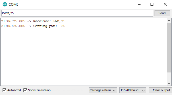
In the Arduino IDE you can open the Serial Monitor under the tools menu. In the text box type the command (PWM) and the speed data separated by a command then then click the send button.
Example: PWM,25
This will set the hoverboard motor speed to about 10% (25 / 255).
/*   PWM_Serial
 *   Changes the PWM via Serial commands
 *
 *   created 2021
 *   Mad-EE  (Mad Electrical Engineer)
 *   www.mad-ee.com
 *
 *   This example code is in the public domain.
 *
 *   Platform:  Arduino UNO
 */

// Constants
const double BAUD_RATE = 115200;              // Serial port baud rate
const unsigned int BUFFER_SIZE = 16;          // Serial receive buffer size

// Pin declarations for UNO board
const int PIN_PWM = 9;                        // 490Hz pins 3, 9, 10, 11

// Variables used in ReadFromSerial function
String _command = "";                         // Command received in Serial read command
int _data = 0;                                // Data received in Serial read command

void setup()
{
    // Set PWM pins to outputs
    pinMode(PIN_PWM, OUTPUT);

    // Initialize PWM to off
    analogWrite(PIN_PWM, 0);

    // Initialize serial port
    Serial.begin(BAUD_RATE);
    Serial.println("---- Program Started ----");
}

void loop()
{
    // Read serial data and set dataReceived to true if command is ready to be processed
    bool dataReceived = ReadFromSerial();

    // Process the received command if available
    if (dataReceived == true)
        ProcessCommand(_command, _data);
}

// Receives string data from the serial port
// Data should be in the format <command>,<data>
// Data should be terminated with a carriage return
// Function returns true if termination character received
bool ReadFromSerial()
{
    // Local variables
    static String cmdBuffer;        // Stores the received command
    static String dataBuffer;       // Stores the received data
    static bool isCommand = true;   // Flag to store received bytes in command or data buffer
    byte recByte;                   // Byte received from the serial port

    // Check if any new data is available, if not exit
    if (Serial.available() == false)
        return false;

    // Read single byte from serial port
    recByte = Serial.read();

    // Check if byte is termination character (carriage return)
    if (recByte == '\r')
    {
        // Save buffers to global variables
        cmdBuffer.toUpperCase();
        _command = cmdBuffer;
        _data = dataBuffer.toInt();

        // Write what was received back to the serial port
        Serial.print("Received: ");
        Serial.print(_command);
        Serial.print(",");
        Serial.println(_data);

        // Clear local variables
        cmdBuffer = "";
        dataBuffer = "";
        isCommand = true;

        return true;
    }

    // Check if byte is a comma which separates the command from the data
    if ((char)recByte == ',')
    {
        isCommand = false;  // Next byte will be a data byte
        return false;
    }

    // Save data to one of the receive buffers
    if (isCommand)
        cmdBuffer += (char)recByte;
    else
        dataBuffer += (char)recByte;

    return false;
}

// Processes the command and data, sends result to serial port
void ProcessCommand(String command, int data)
{
    // Process PWM command
    if (command == "PWM")
    {
      Serial.print("Setting pwm:  ");
      Serial.println(data);
      analogWrite(PIN_PWM, data);
    }
}
Reading Motor Speed
The motor controller board outputs a frequency on the S pin of the auxiliary port porportional to the speed of the motor. For detailed analysis of this signal refer to my previous post here:
https://mad-ee.com/easy-inexpensive-hoverboard-motor-controller/#speedpulseoutput
Synchronous Measurement
An easy method to measure the frequency on a pin is to use the pulseIn() command. The pulseIn command measures the amount of time, in microseconds, a signal on a pin is either high or low. The problem with this command is it is a blocking command. This means that you can not run any other code while this command is processing the signal. Depending on your application this may or may not cause issues.
More information on the pulseIn command can be found here:
https://docs.arduino.cc/language-reference/en/functions/advanced-io/pulseIn/
Example Program – Hoverboard_Speed_Sync
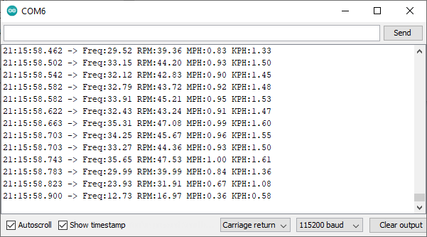
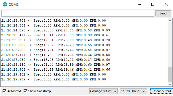
This example code uses the pulseIn command to measure the on time of a the speed signal and calculates the frequency of that signal (assuming 50% duty cycle). It then calculates and outputs to the serial port the frequency, Revolutions Per Minute(RPM), Miles Per Hour (MPH), and Kilometers Per Hour (KPH). The MPH and KPH are based on the wheel diameter or circumference, which are defined constants at the top of the code. I measured the circumference of my wheel by wrapping a string around the outer diameter and then measuring it with a tape measure.
In the Arduino IDE open the serial monitor and run the code. You can turn the wheel by hand and it will output the speed data to the serial monitor.
/*   Hoverboard_Speed_Sync
 *   Measures the speed of a hoverboard motor synchronously
 *   using the pulseIn function.  Uses the SC speed pulse output of the
 *   RioRand 400W 6-60V PWM DC Brushless Electric Motor Speed Controller with Hall.
 *   Outputs the speed data to the serial port.
 *
 *   created 2021
 *   Mad-EE  (Mad Electrical Engineer)
 *   www.mad-ee.com
 *
 *   This example code is in the public domain.
 *
 *   Platform:  Arduino UNO
 */

// Constants
const double BAUD_RATE = 115200;  // Serial port baud rate
const double WHEEL_DIAMETER_IN = 6.5;            // Motor wheel diamater (inches)
const double WHEEL_CIRCUMFERENCE_IN = 22.25;     // Motor wheel circumference (inches)
const double WHEEL_DIAMETER_CM = 16.5;           // Motor wheel diamater (centimeters)
const double WHEEL_CIRCUMFERENCE_CM = 56.5;      // Motor wheel circumference (centimeters)

// Pin declarations for UNO board
const int PIN_SPEED = 12;         // SC Speed Pulse Output from RioRand board

void setup()
{
    // Set pin directions
    pinMode(PIN_SPEED, INPUT);

    // Initialize serial port
    Serial.begin(BAUD_RATE);
    Serial.println("---- Program Started ----");
}

void loop()
{
    double freq = 0;
    double rpm = 0;
    double mph = 0;
    double kph = 0;

    // Measure the time the pulse is Hi
    // If pulseIn times out then ontime will equal 0
    unsigned long ontime = pulseIn(PIN_SPEED, HIGH);

    // Only run calculations if ontime > 0
    if (ontime > 0)
    {
        // Calculate the period of the signal
        unsigned long period = ontime * 2;

        // Calculate the frequency
        freq = 1000000.0 / period;

        // Calculate the revolutions per minute
        rpm = freq / 45 * 60;

        // Calculate the miles per hour (mph) based on the wheel diameter or circumference
        //mph = (WHEEL_DIAMETER_IN * PI * rpm * 60) / 63360;
        mph = (WHEEL_CIRCUMFERENCE_IN * rpm * 60) / 63360;

        // Calculate the miles per hour (kph) based on the wheel diameter or circumference
        //kph = (WHEEL_DIAMETER_CM * PI * rpm * 60) / 1000;
        kph = (WHEEL_CIRCUMFERENCE_CM * rpm * 60) / 100000;
    }

    // Write data to the serial port
    Serial.print((String)"Freq:" + freq + " ");
    Serial.print((String)"RPM:" + rpm + " ");
    Serial.print((String)"MPH:" + mph + " ");
    Serial.println((String)"KPH:" + kph + " ");
}
Asynchronous Measurement
I really don’t like commands that block execution of code while waiting on something. So instead of using the pulseIn command I wrote another function (ReadSpeed) that monitors the speed pin and measures the amount of time between state changes. When the pin changes state it calculates the frequency, rpm, mph, and kph. It saves those calculations to global variables. The global variables are then written to the serial port output at a constant rate.
In the Arduino IDE open the serial monitor and run the code. Like the synchronous code you can turn the wheel by hand and it will output the speed data to the serial monitor, but this time the serial output will print at a constant rate.
/*   Hoverboard_Speed_Async
 *   Measures the speed of a hoverboard motor asynchronously
 *   using a custom ReadSpeed function.  Uses the SC speed pulse output of the
 *   RioRand 400W 6-60V PWM DC Brushless Electric Motor Speed Controller with Hall.
 *   Outputs the speed data to the serial port.
 *
 *   created 2021
 *   Mad-EE  (Mad Electrical Engineer)
 *   www.mad-ee.com
 *
 *   This example code is in the public domain.
 *
 *   Platform:  Arduino UNO
 */

// Constants
const unsigned long SPEED_TIMEOUT = 500000;   // Time used to determine wheel is not spinning
const unsigned int UPDATE_TIME = 500;         // Time used to output serial data
const unsigned int BUFFER_SIZE = 16;          // Serial receive buffer size
const double BAUD_RATE = 115200;              // Serial port baud rate
const double WHEEL_DIAMETER_IN = 6.5;            // Motor wheel diamater (inches)
const double WHEEL_CIRCUMFERENCE_IN = 22.25;     // Motor wheel circumference (inches)
const double WHEEL_DIAMETER_CM = 16.5;           // Motor wheel diamater (centimeters)
const double WHEEL_CIRCUMFERENCE_CM = 56.5;      // Motor wheel circumference (centimeters)

// Pin Declarations
const int PIN_SPEED = 12;

// Variables used in ReadSpeed function
double _freq;               // Frequency of the signal on the speed pin
double _rpm;                // Wheel speed in revolutions per minute
double _mph;                // Wheel speed in miles per hour
double _kph;                // Wheel speed in kilometers per hour

// This is ran only once at startup
void setup()
{
    // Set pin directions
    pinMode(PIN_SPEED, INPUT);

    // Initialize serial port
    Serial.begin(BAUD_RATE);
    Serial.println("---- Program Started ----");
}

// This is the main program loop that runs repeatedly
void loop()
{
    // Read the speed from input pin (sets _freq, _rpm, _mph, _kph)
    ReadSpeed();

    // Outputs the speed data to the serial port
    WriteToSerial();
}

// Reads the speed from the input pin and calculates RPM and MPH
// Monitors the state of the input pin and measures the time (µs) between pin transitions
void ReadSpeed()
{
    static bool lastState = false;    // Saves the last state of the speed pin
    static unsigned long last_uS;     // The time (µs) when the speed pin changes
    static unsigned long timeout_uS;  // Timer used to determine the wheel is not spinning

    // Read the current state of the input pin
    bool state = digitalRead(PIN_SPEED);

    // Check if the pin has changed state
    if (state != lastState)
    {
      // Calculate how long has passed since last transition
      unsigned long current_uS = micros();
      unsigned long elapsed_uS = current_uS - last_uS;

      // Calculate the frequency of the input signal
      double period_uS = elapsed_uS * 2.0;
      _freq = (1 / period_uS) * 1E6;

      // Calculate the RPM
      _rpm = _freq / 45 * 60;

      // If RPM is excessively high then ignore it.
      if (_rpm > 5000) _rpm = 0;

      // Calculate the miles per hour (mph) based on the wheel diameter or circumference
      //_mph = (WHEEL_DIAMETER_IN * PI * _rpm * 60) / 63360;
      _mph = (WHEEL_CIRCUMFERENCE_IN * _rpm * 60) / 63360;

      // Calculate the miles per hour (kph) based on the wheel diameter or circumference
      //_kph = (WHEEL_DIAMETER_CM * PI * _rpm * 60) / 1000;
      _kph = (WHEEL_CIRCUMFERENCE_CM * _rpm * 60) / 100000;

      // Save the last state and next timeout time
      last_uS = current_uS;
      timeout_uS = last_uS + SPEED_TIMEOUT;
      lastState = state;
    }
    // If too long has passed then the wheel has probably stopped
    else if (micros() > timeout_uS)
    {
        _freq = 0;
        _rpm = 0;
        _mph = 0;
        _kph = 0;
        last_uS = micros();
    }
}

// Writes the RPM and MPH to the serial port at a set interval
void WriteToSerial()
{
    // Local variables
    static unsigned long updateTime;

    if (millis() > updateTime)
    {
        // Write data to the serial port
        Serial.print((String)"Freq:" + _freq + " ");
        Serial.print((String)"RPM:" + _rpm + " ");
        Serial.print((String)"MPH:" + _mph + " ");
        Serial.println((String)"KPH:" + _kph + " ");

        // Calculate next update time
        updateTime = millis() + UPDATE_TIME;
    }
}
Final Code
Lets put all that code together to create a program that can control a single hoverboard motor via commands form the serial port. We will add in commands for the brake and to change the direction of the motor along with measuring the speed of the motor asynchronously.
As mentioned before the commands are in this format:
<command>,<data>,<CR>
The supported commands are:
- PWM – Changes the speed of the motor. data = 0 – 255
- Example: PWM, 127
- BRAKE – Enables and disables the brake. data = 0 or 1
- Example: BRAKE,1
- DIR – Changes the direction of the motor. data = 0 or 1
- Example: DIR,1
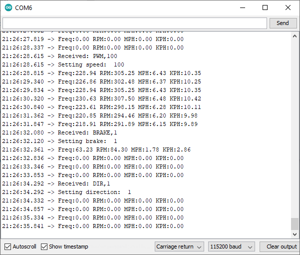
In the serial monitor window you will see the speed output like with the asynchronous code. You can also send the PWM, BRAKE, and DIR commands to the Arduino.
/*   Hoverboard_Serial_Test
 *   Controls the speed, brake, and direction of a single hoverboard motor
 *   via commands sent through the serial port.
 *   Measures the speed of a hoverboard motor asynchronously
 *   using a custom ReadSpeed function.  Uses the SC speed pulse output of the
 *   RioRand 400W 6-60V PWM DC Brushless Electric Motor Speed Controller with Hall.
 *   Outputs the speed data to the serial port.
 *
 *   created 2021
 *   Mad-EE  (Mad Electrical Engineer)
 *   www.mad-ee.com
 *
 *   This example code is in the public domain.
 *
 *   Platform:  Arduino UNO
 */

// Constants
const unsigned long SPEED_TIMEOUT = 500000;       // Time used to determine wheel is not spinning
const unsigned int UPDATE_TIME = 500;             // Time used to output serial data
const unsigned int BUFFER_SIZE = 16;              // Serial receive buffer size
const double BAUD_RATE = 115200;                  // Serial port baud rate
const double WHEEL_DIAMETER_IN = 6.5;            // Motor wheel diamater (inches)
const double WHEEL_CIRCUMFERENCE_IN = 22.25;     // Motor wheel circumference (inches)
const double WHEEL_DIAMETER_CM = 16.5;           // Motor wheel diamater (centimeters)
const double WHEEL_CIRCUMFERENCE_CM = 56.5;      // Motor wheel circumference (centimeters)

// Pin Declarations
const int PIN_DIR = 2;      // Motor direction signal
const int PIN_BRAKE = 3;    // Motor brake signal (active low)
const int PIN_PWM = 9;      // PWM motor speed control
const int PIN_SPEED = 12;   // SC Speed Pulse Output from RioRand board

// Variables used in ReadFromSerial function
String _command = "";       // Command received in Serial read command
int _data = 0;              // Data received in Serial read command

// Variables used in ReadSpeed function
double _freq;               // Frequency of the signal on the speed pin
double _rpm;                // Wheel speed in revolutions per minute
double _mph;                // Wheel speed in miles per hour
double _kph;                // Wheel speed in kilometers per hour

// This is ran only once at startup
void setup()
{
    // Set pin directions
    pinMode(PIN_SPEED, INPUT);
    pinMode(PIN_PWM, OUTPUT);
    pinMode(PIN_BRAKE, OUTPUT);
    pinMode(PIN_DIR, OUTPUT);

    // Set initial pin states
    digitalWrite(PIN_BRAKE, false);
    digitalWrite(PIN_DIR, false);
    analogWrite(PIN_PWM, 0);

    // Initialize serial port
    Serial.begin(BAUD_RATE);
    Serial.println("---- Program Started ----");
}

// This is the main program loop that runs repeatedly
void loop()
{
    // Read serial data and set dataReceived to true if command is ready to be processed
    bool dataReceived = ReadFromSerial();

    // Process the received command if available
    if (dataReceived == true)
        ProcessCommand(_command, _data);

    // Read the speed from input pin (sets _rpm and _mph)
    ReadSpeed();

    // Outputs the speed data to the serial port
    WriteToSerial();
}

// Receives string data from the serial port
// Data should be in the format <command>,<data>
// Data should be terminated with a carriage return
// Function returns true if termination character received
bool ReadFromSerial()
{
    // Local variables
    static String cmdBuffer;        // Stores the received command
    static String dataBuffer;       // Stores the received data
    static bool isCommand = true;   // Flag to store received bytes in command or data buffer
    byte recByte;                   // Byte received from the serial port

    // Check if any new data is available, if not exit
    if (Serial.available() == false)
      return false;

    // Read single byte from serial port
    recByte = Serial.read();

    // Check if byte is termination character (carriage return)
    if (recByte == '\r')
    {
        // Save buffers to global variables
        cmdBuffer.toUpperCase();
        _command = cmdBuffer;
        _data = dataBuffer.toInt();

        // Write what was received back to the serial port
        Serial.print("Received: ");
        Serial.print(_command);
        Serial.print(",");
        Serial.println(_data);

        // Clear local variables
        cmdBuffer = "";
        dataBuffer = "";
        isCommand = true;

        return true;
    }

    // Check if byte is a comma which separates the command from the data
    if ((char)recByte == ',')
    {
        isCommand = false;  // Next byte will be a data byte
        return false;
    }

    // Save data to one of the receive buffers
    if (isCommand)
        cmdBuffer += (char)recByte;
    else
        dataBuffer += (char)recByte;

    return false;
}

// Processes the command and data, sends result to serial port
void ProcessCommand(String command, int data)
{
    // Process SPEED command
    if (command == "PWM")
    {
      Serial.print("Setting speed:  ");
      Serial.println(data);
      analogWrite(PIN_PWM, data);
    }

    // Process BRAKE command
    if (command == "BRAKE")
    {
      Serial.print("Setting brake:  ");
      Serial.println(data);
      digitalWrite(PIN_BRAKE, data);
    }

    // Process DIR command
    if (command == "DIR")
    {
      Serial.print("Setting direction:  ");
      Serial.println(data);
      digitalWrite(PIN_DIR, data);
    }
}

// Reads the speed from the input pin and calculates RPM and MPH
// Monitors the state of the input pin and measures the time (µs) between pin transitions
void ReadSpeed()
{
    static bool lastState = false;    // Saves the last state of the speed pin
    static unsigned long last_uS;     // The time (µs) when the speed pin changes
    static unsigned long timeout_uS;  // Timer used to determine the wheel is not spinning

    // Read the current state of the input pin
    bool state = digitalRead(PIN_SPEED);

    // Check if the pin has changed state
    if (state != lastState)
    {
      // Calculate how long has passed since last transition
      unsigned long current_uS = micros();
      unsigned long elapsed_uS = current_uS - last_uS;

      // Calculate the frequency of the input signal
      double period_uS = elapsed_uS * 2.0;
      _freq = (1 / period_uS) * 1E6;

      // Calculate the RPM
      _rpm = _freq / 45 * 60;

      // If RPM is excessively high then ignore it.
      if (_rpm > 5000) _rpm = 0;

      // Calculate the miles per hour (mph) based on the wheel diameter or circumference
      //_mph = (WHEEL_DIAMETER_IN * PI * _rpm * 60) / 63360;
      _mph = (WHEEL_CIRCUMFERENCE_IN * _rpm * 60) / 63360;

      // Calculate the miles per hour (kph) based on the wheel diameter or circumference
      //_kph = (WHEEL_DIAMETER_CM * PI * _rpm * 60) / 1000;
      _kph = (WHEEL_CIRCUMFERENCE_CM * _rpm * 60) / 100000;

      // Save the last state and next timeout time
      last_uS = current_uS;
      timeout_uS = last_uS + SPEED_TIMEOUT;
      lastState = state;
    }
    // If too long has passed then the wheel has probably stopped
    else if (micros() > timeout_uS)
    {
        _freq = 0;
        _rpm = 0;
        _mph = 0;
        _kph = 0;
        last_uS = micros();
    }
}

// Writes the RPM and MPH to the serial port at a set interval
void WriteToSerial()
{
    // Local variables
    static unsigned long updateTime;

    if (millis() > updateTime)
    {
        // Write data to the serial port
        Serial.print((String)"Freq:" + _freq + " ");
        Serial.print((String)"RPM:" + _rpm + " ");
        Serial.print((String)"MPH:" + _mph + " ");
        Serial.println((String)"KPH:" + _kph + " ");

        // Calculate next update time
        updateTime = millis() + UPDATE_TIME;
    }
}
Conclusion
I hope these example programs are useful. They demonstrate a few different ways an Arduino can interface to the RioRand motor controller. As with all code there are multiple ways to accomplish the same thing. For example one could use pin interrupts to measure the speed signal form the board. This is another good way that doesn’t use the blocking pulseIn command and allows the microcontroller to run other code while waiting for changes in the speed signal.
If you are working on any projects using the RioRand and an Arduino, post a command and tell me about it, I like to hear what others are doing.
Cheers!