
Table of Contents
Introduction
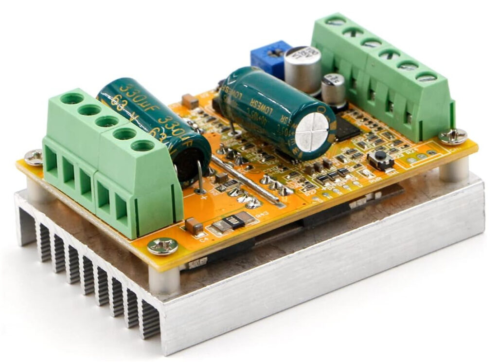
This brushless electric motor driver is inexpensive and easy to use to control a hoverboard motor.
A little backstory on how I found this driver. A coworker of mine sent me a video of a guy that made a giant remote control spider for Halloween. After watching the video I decided I wanted to make a remote control robotic platform that I could drive around the neighborhood. I wanted it to be able to support a good amount of weight, maybe even give rides to my kids on it. The giant spider was made on radio controlled truck chassis. This had two problems, the first is it couldn’t support much weight, and the second was that RC truck cost around $1000, which was way outside my budget for a home project.
One day on my way home from work I decided to stop at Wal-Mart and just look at the RC vehicles. They didn’t have much and I was about to leave when I spotted the hoverboards. My first thought was “YES, those can do what I want.” They are designed to support a good amount of weight and travel at a good speed. I knew there had to be a way to control them.
I started searching the internet and found that there are some people that have hacked the control board firmware. I started going down that path and I ordered the Hover-1 Eclipse.
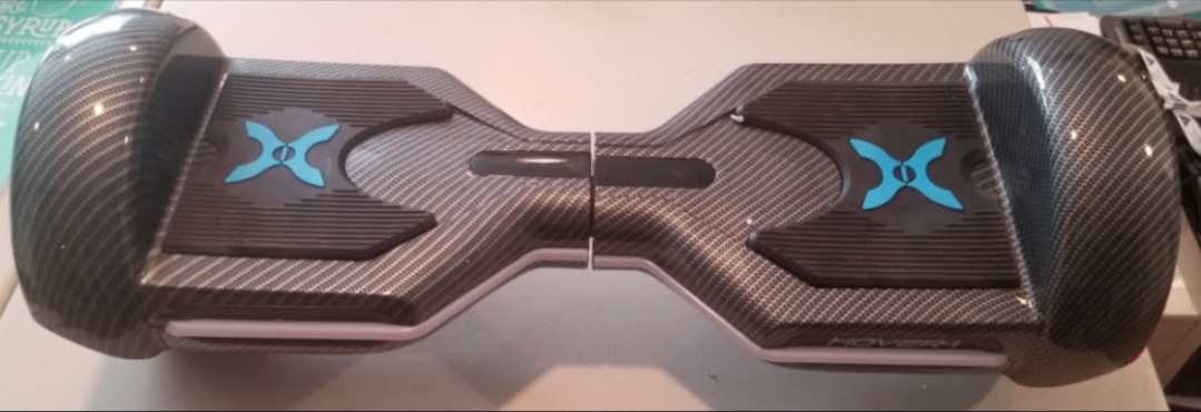
After I received the hoverboard of course I had to play around on it and try to figure out how to ride it. It was kind of fun until I fell a couple times and I decided I’m too old for that stuff and I’m going to do some damage that is going to be hard to recover from. So I took it apart.
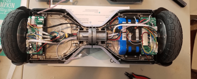
I started messing with the firmware and didn’t get too far when I found an inexpensive brushless electric motor driver on Amazon. I ordered one of those and I was able to get up and running much faster than hacking the firmware.
YouTube Video
I made a YouTube video on how the driver board works. You can watch it here:
Controller Description
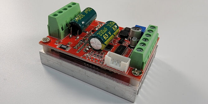
This RioRand motor speed controller board is designed to work with a three-phase brushless DC motors with hall sensors. The part number printed on the board is ZS-Z11H. There is another version of this board that is designed to work with motors without hall sensors. The part number printed on that board is ZS-X11F. Each of these boards go for around $20 on Amazon or E-Bay.
As an Amazon Associate, I earn from qualifying purchases.
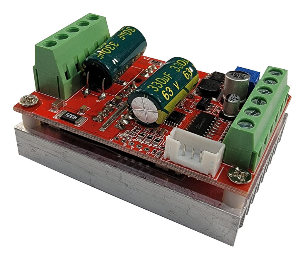
The ZS-X11H board with hall sensors works perfectly for driving a hoverboard motor. It has all the connections to provide power to the motor and also connections to control the speed, brake, and direction. It is relatively easy to connect an Arduino or Raspberry Pi to control the board or other micro-controller device.
Board Version
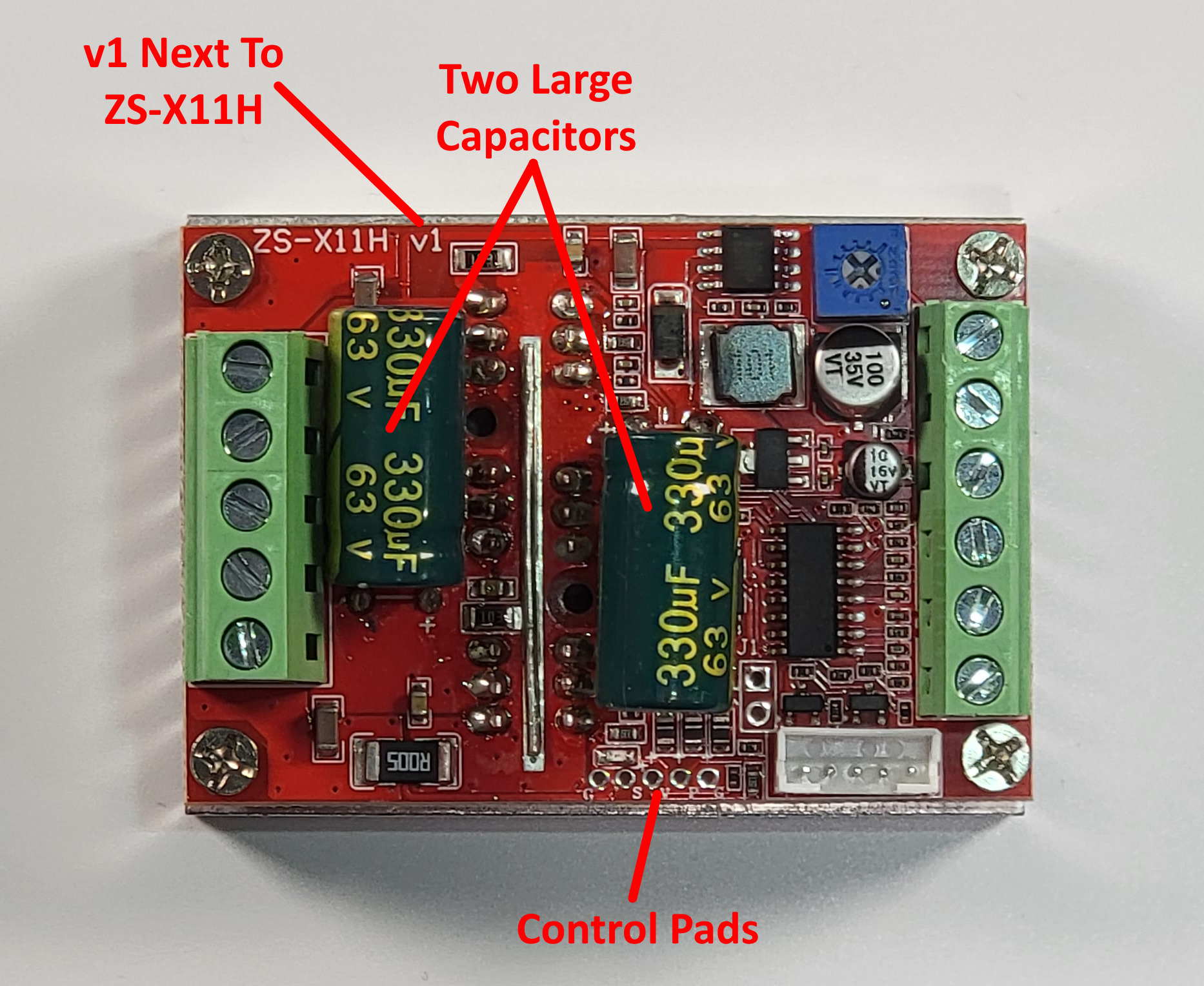
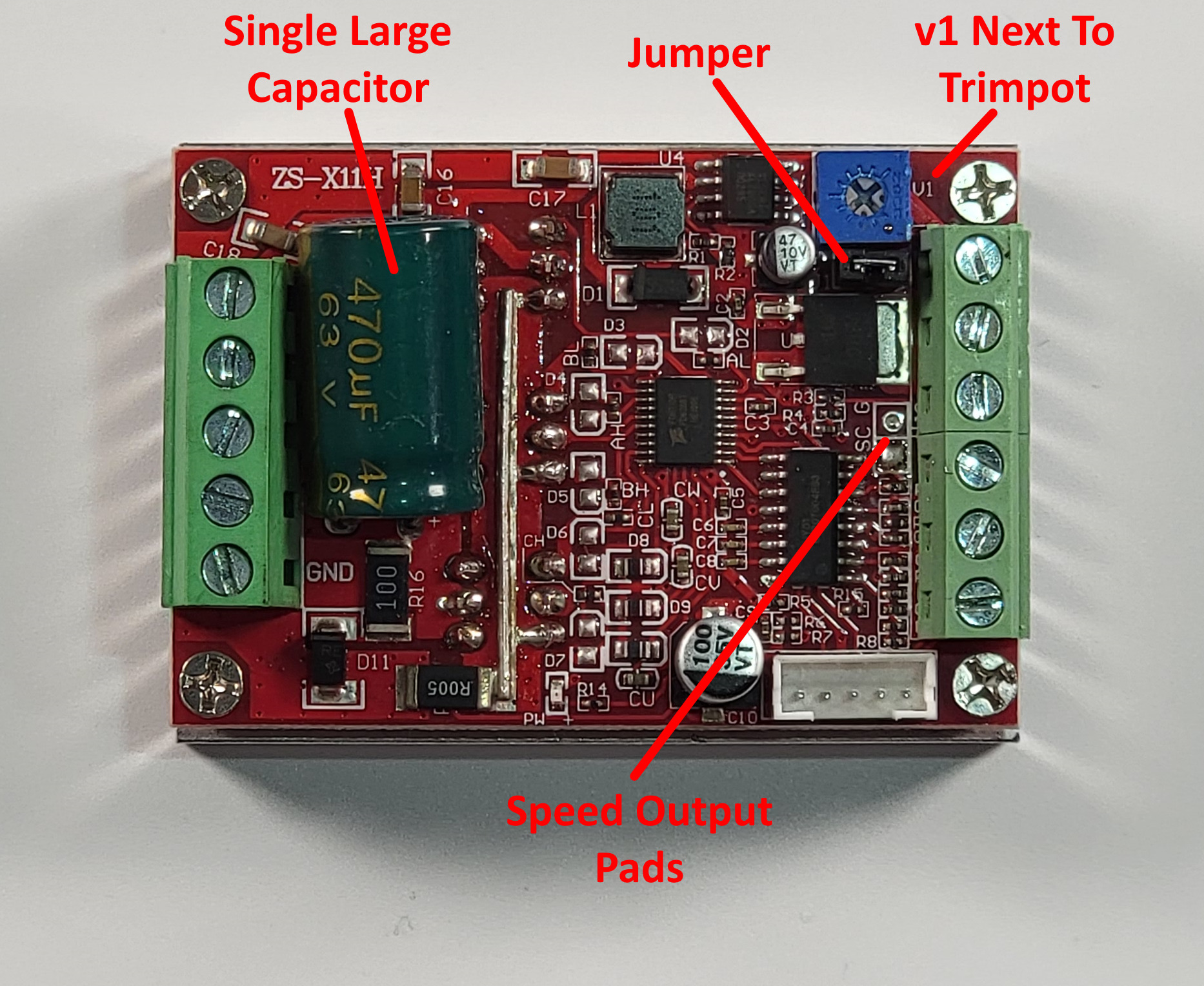
There are two version of this board. The company that made the board updated it and changed some of its features. See the images below on how to identify which version you have.
This guide focuses on the new version of the board. I made a very rough video about a year ago about the old version of the board. You can watch it here:
New Version
Old Version
Pinout / Connections
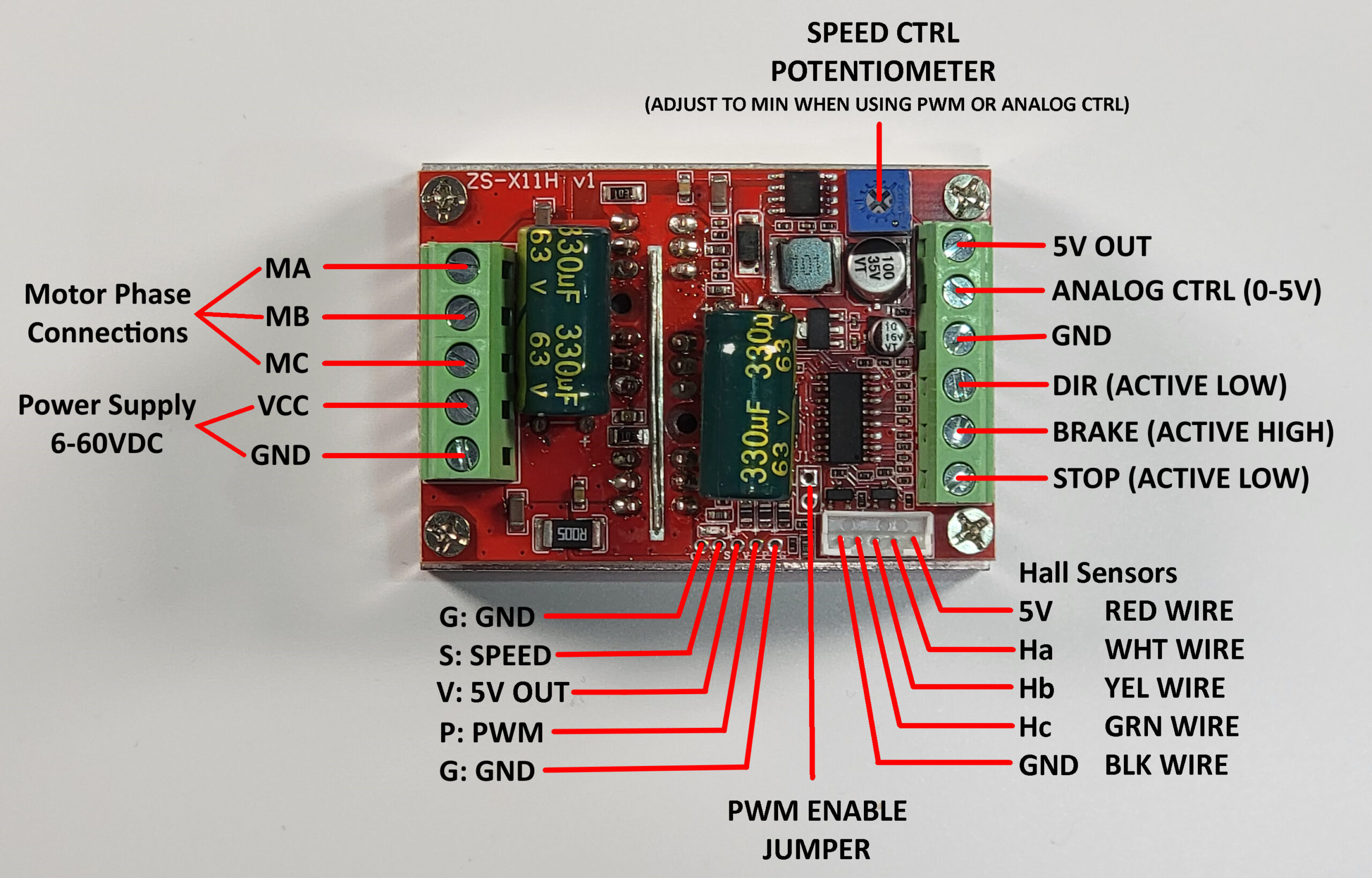
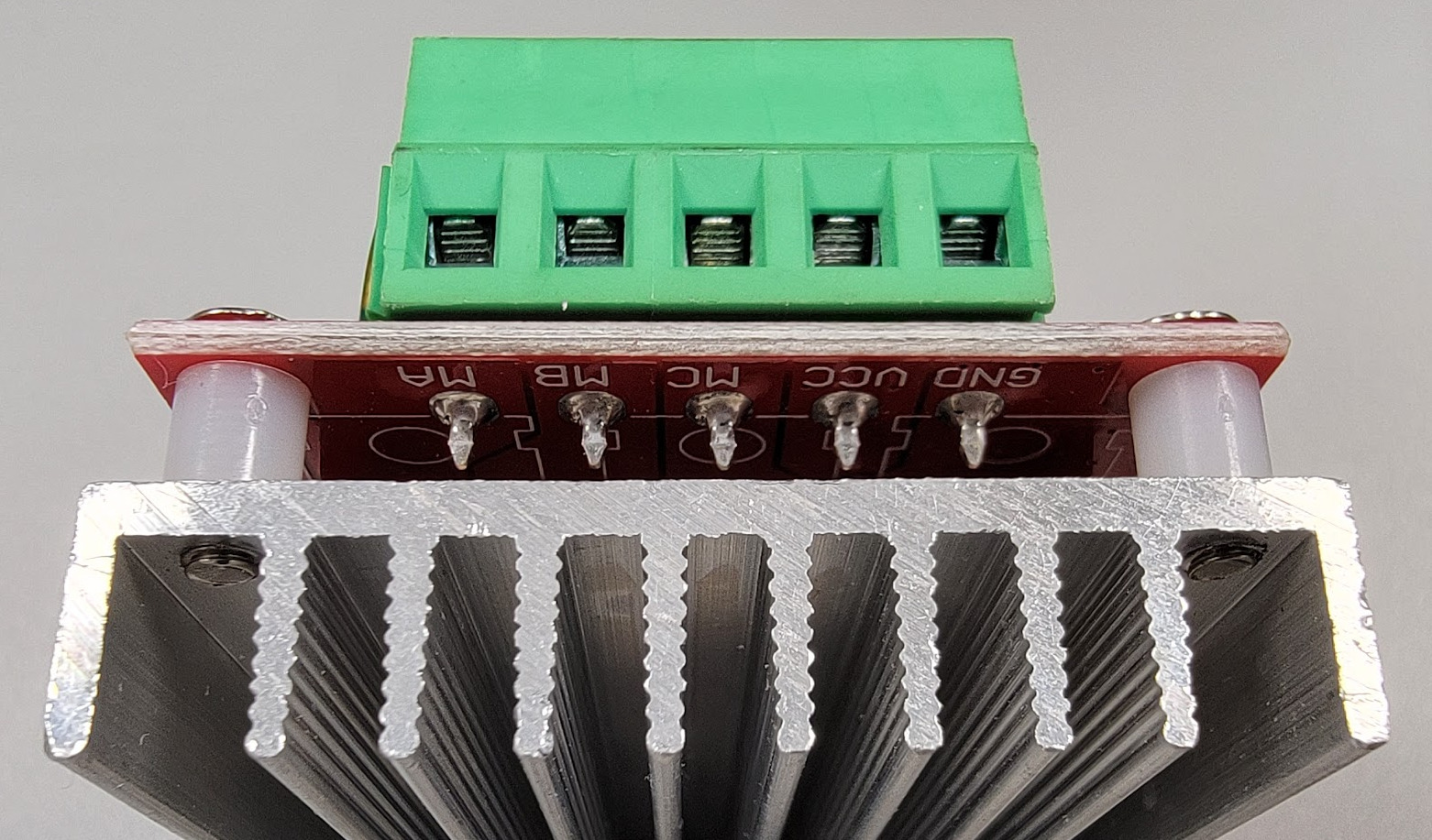
Screw Terminal Connector (Left)
This five pin connector has connections for driving the motors phases and the power supply input.
- MA – Motor Phase A
- MB – Motor Phase B
- MC – Motor Phase C
- VCC – Power Supply Input 6 to 60VDC
- GND – Power Supply Return
The pinout is printed in silk screen on the bottom of the board under the connector.
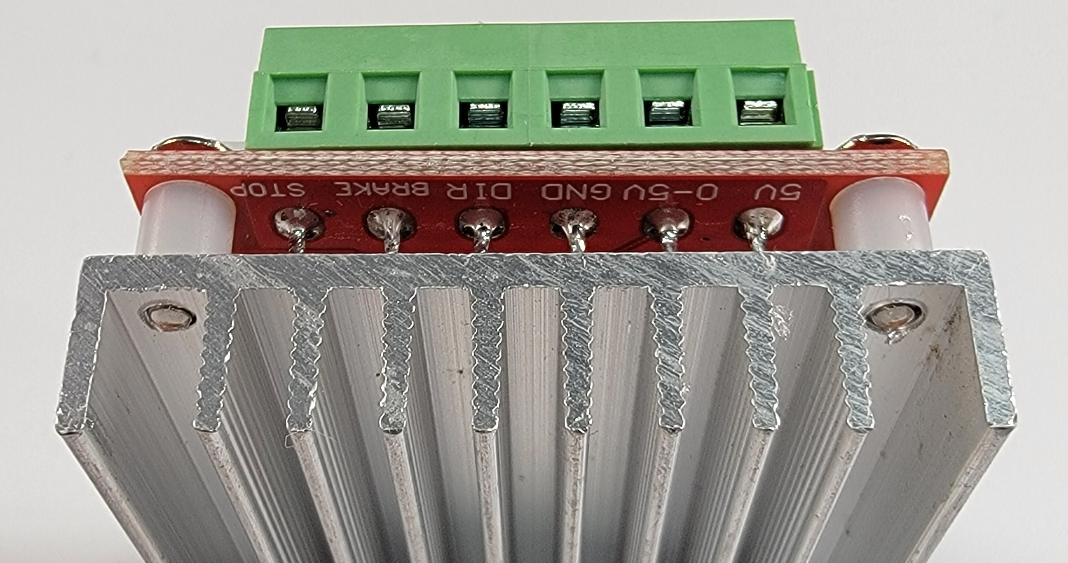
Screw Terminal Connector (right)
This six pin connector has connections for controlling the motor speed, direction, and braking. The board has on onboard 5V 78L05 voltage regulator with a 5V output pin which is intended to be used to power the external potentiometer and to apply voltage to the brake pin through a switch or a relay. There is probably enough overhead on the regulator to also power a small micro-controller board such as an Arduino.
- 5V – Power output from the onboard voltage regulator.
- ANALOG CTRL – Speed control input. 0 to 5V signal that can be driven from the wiper terminal of a potentiometer connected to 5V and ground, or an analog output of a Digital to Analog Converter (DAC).
- GND – Ground connection
- DIR – Direction control. This signal is active low, so shorting it to ground or applying a logic 0 changes the motor direction. Leaving the pin floating or applying a logic 1 will spin the motor in the default direction.
- BRAKE – Controls the motor brake. This signal is active high, so shorting it to 5V or applying a logic 1 will apply the motors brake. Leaving the pin floating or applying a logic 0 will disconnect the brake and allow the motor to spin.
- STOP – Functions as an enable input for the board. This signal is active low, so shorting it to ground or applying a logic 0 will disable the drive signals. This could be considered a coast or free spin mode. Leaving the pin floating or applying a logic high will enable the boards drive signals.
The pinout is printed in silk screen on the bottom of the board under the connector.
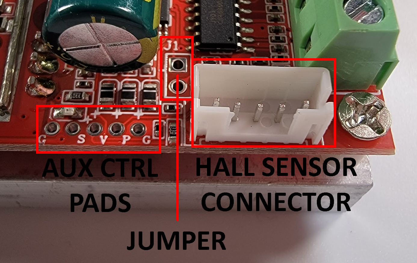
Aux Control Pads and Hall Sensor Connector
The auxiliary control pads allows a user to control the speed of the user using a Pulse Width Modulated (PWM) signal and to read the speed of the motor via the SC speed pulse output interface.
Aux Control Pads:
- G – GND: Ground connection for the auxiliary signals.
- S – SC: Speed pulse output interface. This outputs a pulsed signal that can be used to read the speed of the motor. The documents claim this is a reserved interface and they don’t provide any technical support regarding this signal. See the Speed Pulse Output section for my evaluation of the signal.
- V – 5V: The documentation claims this pin is reserved for a future tachometer. From what I can tell it is just a 5V output that they will use to provide power to the tachometer. It shouldn’t be a problem to use it to power a small micro-controller such as an Arduino just as long as you don’t draw too much power from the pin.
- P – PWM: This pin can be used to control the motor via a Pulse Width Modulated (PWM) signal. The documentation states the frequency can be from 50Hz to 20kHz, with an amplitude of 2.5V to 5V. The typically Arduino PWM signal is either 490Hz or 980Hz so it should be no problem controlling the motor speed via this pin. The PWM Jumper must be shorted and the Speed Control Potentiometer must be adjusted to the minimum when using the PWM control pin.
- G – GND: Ground connection for the auxiliary signals.
PWM Jumper
- J1 Jumper – The J1 jumper is used to connect the PWM control line. To use the PWM for motor control the J1 jumper must be shorted. Also the Speed Control Potentiometer must be adjusted to the minimum.
Hall Sensor Connector – A multi-color cable is provided with the board to connect the motors hall sensors.
- GND – Black wire. Used as a ground for the hall sensors.
- Hc – Green wire. Hall sensor for the motor C phase.
- Hb – Yellow wire. Hall sensor for the motor B phase.
- Ha – White wire. Hall sensor for the motor A phase.
- 5V – Red wire. Hall sensor power.
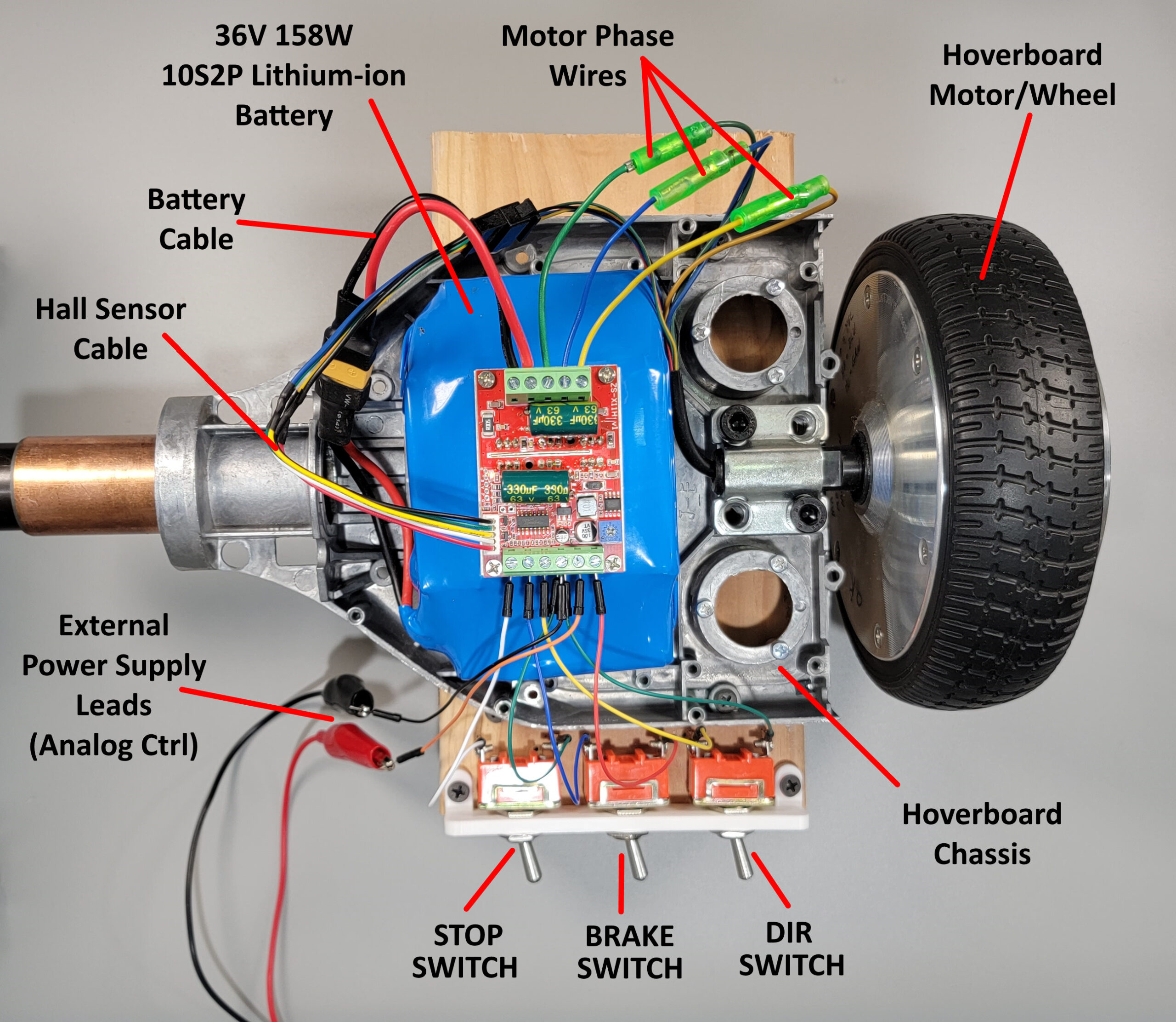
Test Setup
To test the RioRand driver board I built a hoverboard test platform which consists of the following:
- Half of a hoverboard chassis mounted on a couple 2×6 wood blocks to lift the wheel off the table.
- Hoverboard motor/wheel taken out of an old hoverboard.
- 36V 158W Lithium-ion 10S2P Battery
- Stop switch connected to STOP terminal and GND.
- Brake switch connected to the BRAKE terminal and 5V.
- Direction switch connected to the DIR terminal and GND.
- External 0-5V power supply connected to the Analog Ctrl terminal.
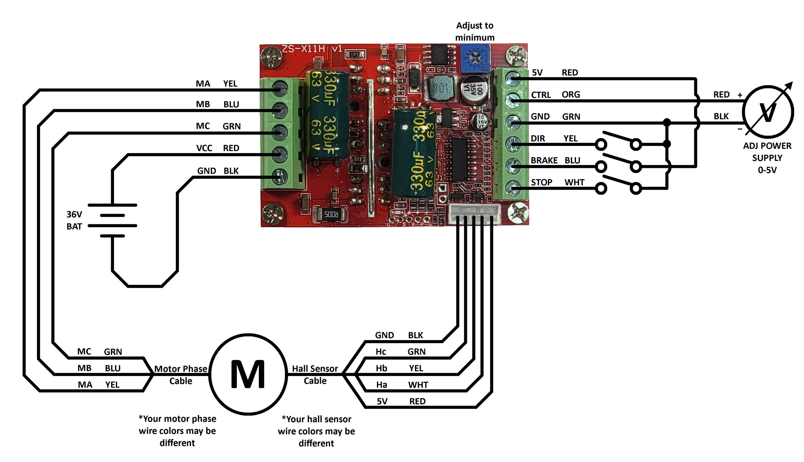
Schematic
Here is the schematic of the hoverboard driver test setup:
Testing
On board potentiometer: To test the on board potentiometer I had to disconnect the adjustable power supply from the analog control screw terminal. Turning the pot clockwise increases the motor speed and counterclockwise decreases the speed.
Analog Control: For testing the analog control the on board potentiometer should be turned all the way counterclockwise so it does not interfere with the analog signal. The motor starts to slowly turn around 0.07V. As expected increasing the voltage increases the motor speed up to a maximum of 5V. I didn’t go above 5V in fear of damaging the board.
Stop Switch: The stop switch disconnects the motor drive signals. If the motor is spinning flipping the switch will cause the motor to coast to a stop. You can easily rotate the motor by hand with the stop switch engaged. Turning off the stop switch reengages the motor drive signals and the motor will start spinning again if the drive is active.
Brake Switch: The brake switch quickly stops the motor and prevents it from turning. With the brake engaged there is noticeable resistance if you try to rotate the motor by hand. It is possible to rotate the motor by hand but not very quickly. Turning off the switch disengages the brake and the motor starts spinning again. The brake still functions with the stop switch engaged.
Direction Switch: The direction switch changes the direction the motor spins. With the switch turned off the motor spins counterclockwise. When turned on the motor spins clockwise. Flipping the switch when the motor is at high speed does work but there is big clunk and the whole test setup jumps, I’m sure this is not good on the motor. It would be best to stop the motor or slow it down before changing directions.
PWM Control
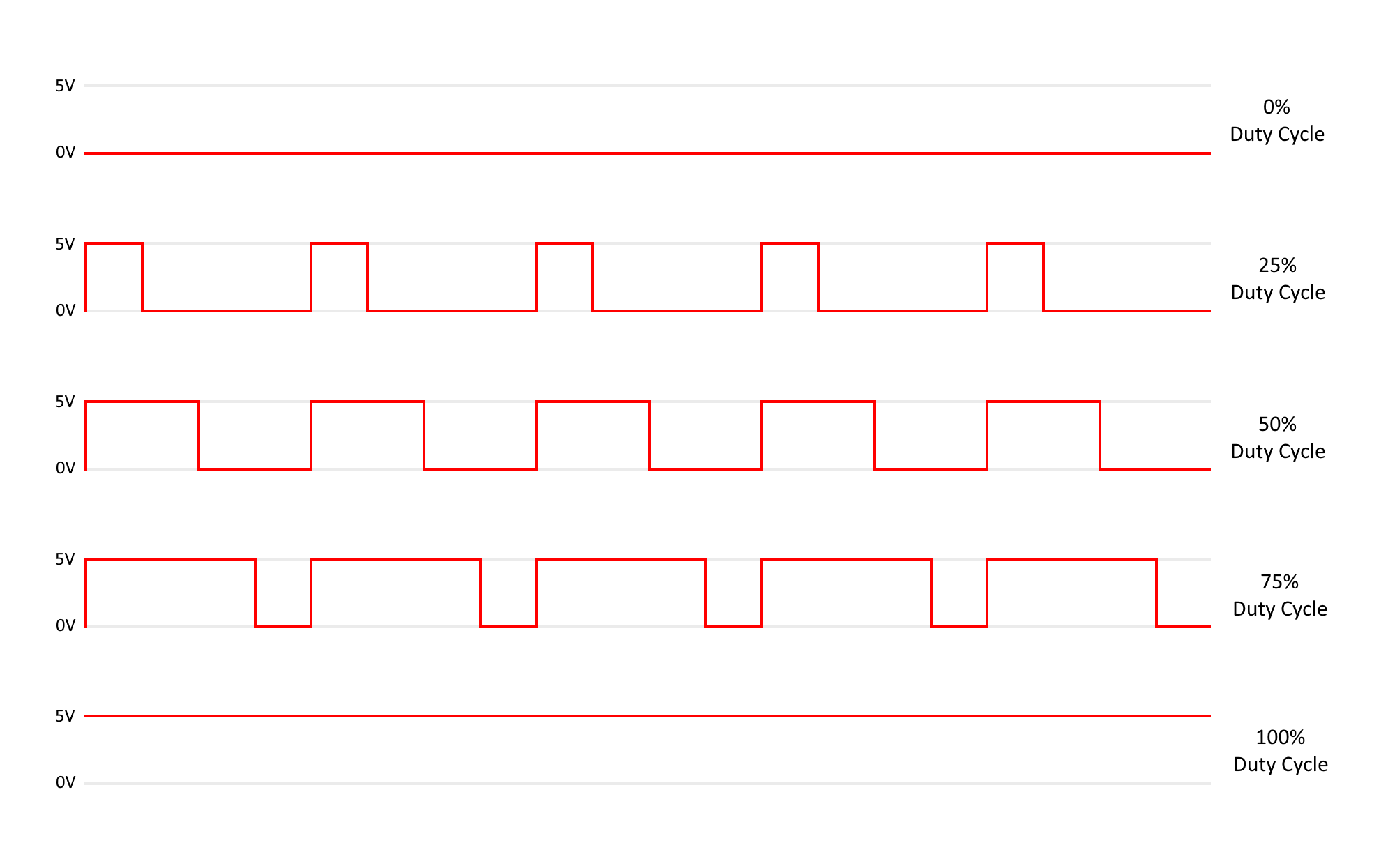
The motor can be controlled using a Pulse Width Modulated (PWM) signal. A PWM signal has a fixed frequency but changes the duty cycle to communicate data. A duty cycle of 0% (constant low) will not drive the motor causing it to be in a free spin. A duty cycle of 100% (constant high) will drive the motor at full speed.
The boards documentation states that a PWM frequency anywhere from 50Hz to 20kHz should work.
To use the PWM input you will need to solder a wire to the P pad of the Auxiliary control pads. You may also need to connect to one of the ground (G) pads if your device generating the PWM signal is not grounded to the board through the screw terminal connector.
You will also need to short the J1 jumper with a wire or a solder blob to connect the PWM signal to the control circuitry. It would have been nice if the board came with a two pin jumper header but unfortunately soldering is required. The speed control potentiometer needs to be adjusted to the off position (counterclockwise) so it does not interfere with the PWM signal.
SC – Speed Pulse Output
The speed pulse output signal is undocumented by the manufacturer. To determine how it works I had to connect a logic analyzer to measure the output signal. The output signal changes state whenever one of the hall sensors changes state. You end up getting 90 state changes for one rotation of the wheel.
Here is the signal recorded by the logic analyzer for one wheel rotation:
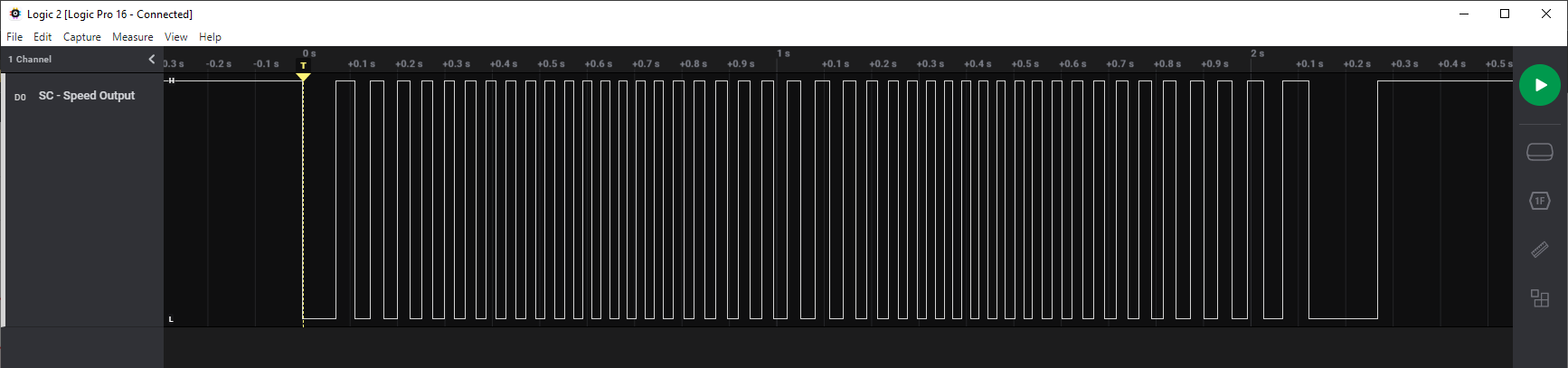
To measure the speed of the wheel all you need to do is measure the time between two transitions (w) and multiply it by 90. This gives you the time is takes for the wheel to rotate one full revolution. You can then calculate revolutions per second (Rps) by taking the inverse of the rotation time. Times that by 60 will give you the revolution per minute (Rpm)
Revolutions Per Second:
Rps = 1 / (w * 90)
Revolutions Per Minute:
Rpm = Rps * 60
Here is an example. I turned the motor drive all the way up to the maximum. Here is the signal from the logic analyzer:
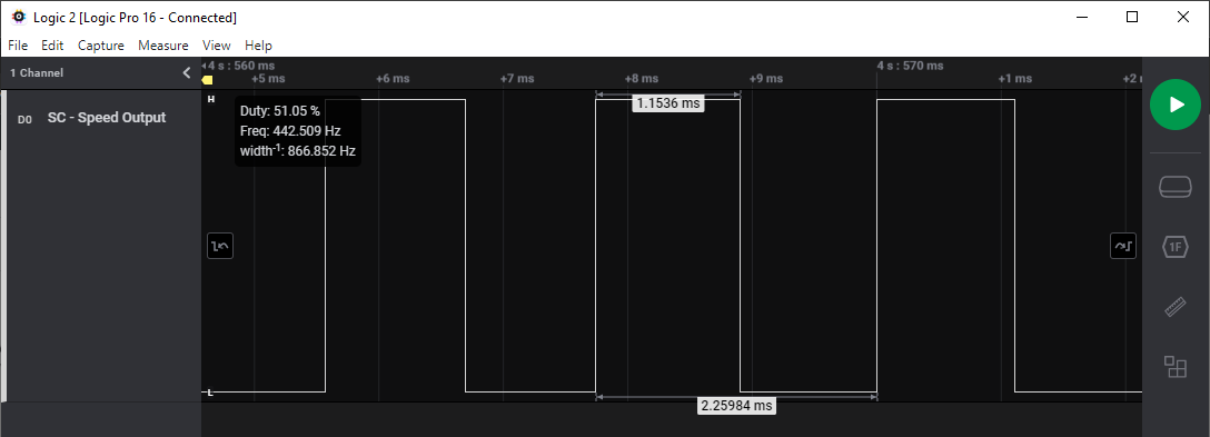
At maximum speed the measured pulse width is 1.1536ms which is 0.0011536 seconds.
RPS = 1/ (0.0011536 * 90)
RPS = 9.632
So the wheel is rotating a little over 9 1/2 times per second. Now I can easily calculate the RPM by multiplying by 60.
RPM = 9.632 * 60
RPM = 577.92
Calculating Miles Per Hour
Sometimes it makes more sense to have the speed in miles per hour. To do this you need to know the wheel diameter (d). Here is the formula to calculate MPH knowing the RPM and wheel diameter (d) in feet:
MPH = (d * π * RPM * 60) / 5280
My hoverboard wheel diameter is about 6.5 inches, which is about 0.542 feet. Working in feet is easier when calculating MPH. Let’s calculate the MPH:
MPH = (0.542 * π * 577.92 * 60) / 5280
MPH = 11.18
So at max speed the wheel is going about 11 miles per hour. Since the wheel is elevated off the table without any resistance this is the unloaded speed. It will probably go slower depending on the load.
Calculating Kilometers Per Hour
Sometimes it makes more sense to have the speed in kilometers per hour. To do this you need to know the wheel diameter (d). Here is the formula to calculate KPH knowing the RPM and wheel diameter (d) in meters:
KPH = (d * π * RPM * 60) / 1000
My hoverboard wheel diameter is about 16.5 centimeters, which is 0.165 meters. Let’s calculate the KPH:
KPH = (0.165 * π * 577.92 * 60) / 1000
KPH = 17.97
So at max speed the wheel is going about 18 kilometers per hour. Since the wheel is elevated off the table without any resistance this is the unloaded speed. It will probably go slower depending on the load.
Conclusion
The RioRand brushless motor driver board works really well to control a hoverboard motor. It has all of the right controls and provides multiple options for controlling the motor speed. The addition of the STOP input was a good change over the previous version which didn’t have it.
There are a couple things RioRand can do better with this board. First they should provide proper documentation for the speed pulse output pin. Second they should populate the J1 jumper with a 2 pin header so the user doesn’t have to solder. Third the auxiliary control pads should also be populated with a 5 pin header, preferable with a 0.1 inch pitch to make it easier for the user to connect to without soldering.
I do recommend those looking to use a hoverboard motor in their projects try out his motor driver. It is inexpensive and easy to use. It can be connected to any micro-controller board such as an Arduino or even to a Raspberry Pi.
1 thought on “Easy Inexpensive Hoverboard Motor Driver”
Comments are closed.